ExtractionOfChiFiles
or how to slice up your diffraction images...
General discussion
Fit2d will be used to obtain slices of the diffraction images as a function of azimuth. Typically, your image shows the Debye-Sherrer rings, slightly distorted because of the deviatoric stress applied to your sample. They run from a azimuth angle delta of 0 to 360.
Typically, in deformation studies, you want to slice your data with a given interval (5 degrees), and, for each angle, have tabulated data with the intensity as a function of the diffraction angle 2 theta.
Multifit assumes that your diffraction data was named with a base and indices, for instance
test_0003.tif
test_0004.tif
test_0005.tif
....
test_0236.tif
where test is the base, test_0003.tif your first image, and test_0236.tif your last image.
You will want to slice up all those images, typically, every 5 degrees for delta between 0 and 360. You will have to create 72 chi files per image, about 16500 chi files total, that will be named as follow
test_0003_0.chi
test_0003_5.chi
test_0003_10.chi
...
test_0003_355.chi
test_0003_360.chi
test_0004_0.chi
...
test_0004_360.chi
...
test_0236_0.chi
...
test_0236_360.chi
Creating a test macro
I do not recommend to go ahead creating the full macro that will create the thousands of chi files without some little testing: do not start with the full range! Do it for a couple of images first (0003 to 0010 in our example, for instance). Make sure everything on this page works, and then create the full macro. Otherwise, you might be overheating your processor for 2 to 3 hours for nothing...
To create your macro, open Data handling -> Create Fit2d Macro for Multiple Files and fill up the form.
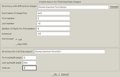
Create a macro for Fit2d
In our case, if we want to slice images 3 to 10, every 5 degrees for azimuth between 0 and 360 degrees, we will enter
- the directory with the diffraction data
- root name for diffraction images:
test - first number:
3 - last number:
10 - number of digits for file numbers:
4 - extension:
.tif - file format: Tiff
- directory with CHI files: set automatically
- first azimuth angle:
0 - last azimuth angle:
360 - interval:
5
It will create a file called test.mac in the data directory. Have a look at it with a text editor: it is the fit2d macro...
Running the macro
In fit2d, exit the powder diffraction interface, and select MACROS / LOG FILES in the main menu (7th item). In the macro interface, select RUN MACRO and open the file that was just created, test.mac in our example.
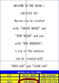
Run a macro in Fit2d
You should see fit2d moving quite a bit, slicing images and so on. In the Fit2d log file, you can follow what is going on (it might go quite fast). Try to make sure that images are loaded properly, and that chi files are also saved properly. For instance, our test_0003_0.chi file should look like
/home/data/Test/test_0003.tif: Azimuth/2-theta
2-Theta Angle (Degrees)
Intensity
        540
 8.9983260E-03  0.0000000E+00
 2.6994979E-02  0.0000000E+00
 4.4991631E-02  0.0000000E+00
 6.2988281E-02  3.1282605E+02
 8.0984935E-02  3.1098578E+02
 9.8981589E-02  3.0880267E+02
 1.1697824E-01  3.1000055E+02
 1.3497490E-01  3.0902777E+02
 1.5297155E-01  3.0717679E+02
...
The first line is the full path to the image. If the full path is not shown, something is wrong!! If you see test_0003.tif instead of /home/.../test_0003.tif or C:\home\...\test_0003.tif on windows, Fit2d did not open your image file: the path was wrong, the name was wrong, the extension was wrong... I don't know, but you have to figure it out.
Second and third lines are labels. Fourth line is the number of points, later on, you have 2 theta in the first column and the intensity in the second column.