|
Texture
In works Memo |
Maud /
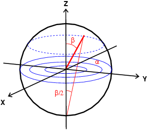
Pole Figures< Define the compression direction | Radial Diffraction | Data Coverage In Axial Diffraction Experiments > Using pole figures to represent directions in spaceDealing with textures and orientations, pole figures become really usefull tools to represent orientations, when you understand what they mean! The two figures below briefly explain how to relate the directions in space to pole figures. The exact relation between the angles alpha and beta and distances on the pole figure plot depends on the type of projection you use. Most common are the sterographic projection and the equal area projection. In the
In experiments performed in compression, the direction of compression usually serves as reference for the Z axis, therefore, we always plot things as a function of their orientation to this direction of compression, Z, which should always be at the center of the pole figure. |

