If you perform a radial diffraction experiment, your incoming x-ray beam is perpendicular to the compression direction. In the figure below, the x-ray beam is
parallel to the Y axis with Y pointing towards the detector. Z is parallel to the compression axis.
We show the location of the data measured at eta=0, eta=90, eta=180 and eta=180 on the pole figure of the compression direction. Eta is the azimuth angle on the image plate. I personaly call it delta in my publications, but MAUD calls it eta...
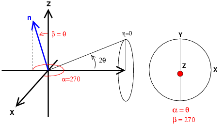 | Figure 1: diffraction in radial geometry with the azimuthal angle on the image plate equals to 0. n is the normal to the diffraction plane and we report the orientation of n on the pole figure. Those planes are nearly perpendicular to the direction of compression. |
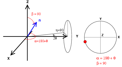 | Figure 2: diffraction in radial geometry with the azimuthal angle on the image plate equals to 90. n is the normal to the diffraction plane and we report the orientation of n on the pole figure. Those planes are parallel to the direction of compression. |
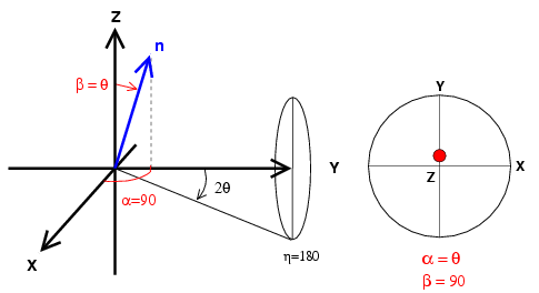 | Figure 3: diffraction in radial geometry with the azimuthal angle on the image plate equals to 180. n is the normal to the diffraction plane and we report the orientation of n on the pole figure. Those planes are nearly perpendicular to the direction of compression |
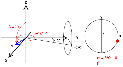 | Figure 4: diffraction in radial geometry with the azimuthal angle on the image plate equals to 270. n is the normal to the diffraction plane and we report the orientation of n on the pole figure. Those planes are parallel to the direction of compression. |
Overall, on a pole figure of the compression direction, one diffraction ring will provide you with the following coverage
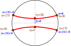 | Figure 5: coverage for diffraction experiments in the radial geometry (in red). Diffractions corresponding to azimuth angles 0, 90, 180, and 360 degrees on the image plate are located in brown on the figure. |


